| United States-English |
|
|
|
HP Integrity Virtual Machines Version 4.0 Installation, Configuration, and Administration > Chapter 8 Creating Virtual NetworksConfiguring VLANs |
|
A local area network (LAN) defines a broadcast domain in which bridges and switches connect all end nodes. Broadcasts are received by every node on the LAN, but not by nodes outside the LAN. A virtual LAN (VLAN) defines logical connectivity instead of the physical connectivity defined by a LAN. A VLAN provides a way to partition a LAN logically such that the broadcast domain for a VLAN is limited to the nodes and switches that are members of the VLAN. VLANs provide the following benefits:
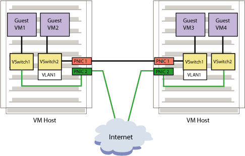
Figure 8-2 illustrates a basic virtual machine VLAN that allows guests on different VM Host systems to communicate. A vNIC on a guest is associated with a port on the vswitch and all network communication to and from the guest passes through this vswitch port. You can configure VLAN rules on the individual ports of the vswitch, similar to most physical switches. Each VLAN is identified by a VLAN identifier (VLAN ID). The VLAN ID is a number in the range 0-4094. A port on the vswitch can be assigned a VLAN ID that identifies the VLAN to which the port (and, therefore, the guest vNIC using that port) belongs. Ports on a vswitch that are configured for the same VLAN ID can communicate with each other. Ports on a vswitch that are configured for different VLAN IDs are isolated from each other. Ports on a vswitch that do not have any VLAN ID assigned cannot communicate with ports that have a VLAN ID assigned, but they can communicate with other ports that have no VLAN ID assigned. If the guest has to communicate with the VM Host or outside the VM Host over a VLAN, additional configuration is necessary. For communication to the VM host, configure a VLAN interface on the VM host interface for that vswitch. This VLAN interface should have the same VLAN ID as the guest port. For information about configuring VLANs on the VM Host, see the Using HP-UX VLANs manual. Do not use the hpvmnet command to create a virtual switch that is associated with a VLAN port on the VM Host (that is, a LAN created with lanadmin -V). This “nested VLAN” configuration is not supported. Frames arriving at the vswitch from a guest can be “tagged” by the vswitch. Tagging consists of inserting the VLAN ID information into the MAC header before forwarding the frame on. Tagged frames destined for a guest are always stripped of the tag information in the frame before being forwarded. For Integrity VM, only tag-unaware guests are supported. To configure a VLAN, follow this procedure:
The following command shows the resulting configuration:
The two virtual machines, vm1 and vm2, have access to the virtual switch vmlan4 and are active on VLAN 100. Specifically, port 1 (guest vm1) and port 2 (guest vm2) can communicate with each other. Port 1 (guest vm1) and port 4 (guest vm2) cannot communicate with each other. The hpvmnet command displays the following information about the VLAN ports:
If you use the hpvmclone command to clone guests, the operation automatically assigns new port numbers for new guests. To assign the same port number to the new guest, use the —S option, as follows:
This command creates a new guest (vmclone1) based on the existing guest vm1, and preserves the vswitch port number so that the new guest will have access to the same VLANs as the existing guest. You can display the vswitches and ports on a vswitch used by a guest using the hpvmstatus command. For example, to display the network information about the guest named vm1, enter the following command:
The preceding example shows the Network Interface Details portion of the hpvmstatus display. In the list of network interfaces, note that each virtual network connection is associated with either port 1 or port 2 of several vswitches. The vswitch named vmlan4 is associated with Bus/Dev/Ftn 0/4/0 on port 1, and with 0/5/0 on port 2. To disable a VLAN, use the following command:
To display information about a specific VLAN port, include the -p option to the hpvmnet command. For example, display VLAN information for port 2 on the vswitch named vmlan4, enter the following command:
To view the all the VLANs defined on the vswitch named vlan4, enter the following command:
When communicating with a remote VM Host or guest over the network, you might need to configure VLANs on the physical switches. The physical switch ports that are used must be configured specifically to allow the relevant VLANs. If the remote host is VLAN aware, You must configure VLAN interfaces on the host for the relevant VLANs. Use thelanadmin command to configure VLANs on a remote HP-UX host. For example, to configure a VLAN interface with VLAN ID 100 on lan4, enter the following command:
|
||||||||||||||||||||||||||||||||||||||||||||||||||||||||||||||||||||||||||||||||||||||||||||||||||
|
|||||||||||||||