|
|

The Cisco INA2320 Setup Tool is designed to guide new users through the initial setup of their Cisco INA2320 Interactive Network Adapter.
When you have finished the initial setup, use the supplied Cisco Cable DVB/DAVIC Management Program to manage the Cisco INA2320, that is, to set all parameters and monitor data traffic.
For detailed information on this process, refer to the Cisco DVB Interactive Network Adapter INA2320 Installation and Configuration Guide before You Start
Cisco recommends that, before you begin the setup, you install the Cisco Cable DVB/DAVIC Management Program and the Cisco INA2320 FTP files on an FTP server.
 |
Tips If you choose not to install the Cisco INA2320 FTP files, you will be able to boot the Cisco INA2320 only from its internal Flash memory. |
A copy of the Cisco Cable DVB/DAVIC Management Program and the Cisco INA2320 FTP files are included on the CD-ROM supplied with the Cisco INA2320. If you have a Cisco service and support contract, these files can also be downloaded from the Cisco website at www.cisco.com >Service & Support > Software Center.
If you intend to use the FTP test function during setup, you must have Microsoft Internet Explorer version 4.x installed on the PC running the setup tool.
 |
Note If you intend to use an FTP server to set up the Cisco INA2320, Cisco recommends that you create an INA account that requires a username and password to log on, because the Cisco INA 2320 does not accept anonymous connections. |
To install the Cisco INA2320 Setup Tool, follow these instructions:
Step 2 Open the folder and read the file readme.txt.
Step 3 Click the relevant version: Windows 9x or Windows NT/2000.
Step 4 Double-click setup.exe and follow the screen instructions.
To uninstall the Cisco INA2320 Setup Tool, follow these instructions:
Step 2 Select Cisco INA2320 Setup Tool and click Remove.
Step 2 If you want to use the FTP test function during setup, ensure that your PC has Microsoft Internet Explorer 4.0 or later.
Step 3 Attach the serial cable from one of the PC's dedicated serial ports (COM1-4) directly to the connector labelled COM on the front plate of the Cisco INA2320's CPU-LAN module.
Step 4 Connect the PC to the same segment of the Ethernet LAN as the Cisco INA2320. When connecting the Cisco INA2320 to a hub or a switch, use a straight-through Ethernet cable. When connecting the Cisco INA2320 directly to your setup PC, use a crossed Ethernet cable.
Step 5 Have details of your FTP server and the "ina" account available (IP address of the FTP server, path, and file name).
To start the application, follow these instructions:
Step 2 Click the Cisco INA2320 Setup Tool desktop shortcut, or choose the application from the Start menu. A program splash page appears, followed by the main screen (see Figure 1). A prompt directs you to click the Start INA Setup button to begin the process. Click OK.
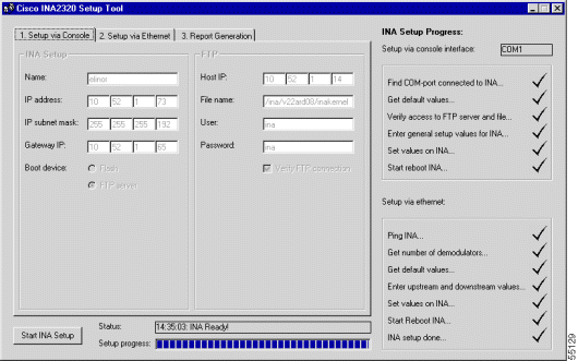
The screen is made up of three main elements:
Step 3 Click Start INA Setup to activate the setup via the Console tab. This tab lets you edit basic INA and FTP setup parameters and to save these parameters using the INA-console connection. You can use the <Prev and Next> buttons to move backward and forward through the fields if you want to make any changes.
Step 4 Power up the Cisco INA2320 (using the black switch on the right side of the front panel). The
Cisco INA2320 Setup Tool now establishes contact with the Cisco INA2320 via your PC's COM port. You can follow its progress by viewing the Status and Setup progress fields at the bottom of the screen.
Step 5 Name: Enter a name for the Cisco INA2320 so that you can identify the device when connecting via the Cisco Cable DVB/DAVIC Management Program, and press Enter to confirm your entry. Use letters and numbers only—special characters are not supported.
Example: Island44
Default: INA001
Step 6 IP Address: Type the IP address you want assign to the Cisco INA2320.
Default: 192.168.1.1
Step 7 IP Subnet Mask: Type the IP subnet mask for the INA IP subnet.
Default: 255.255.255.0
Step 8 Gateway IP: Type the IP address of the default gateway of the Cisco INA2320. This gateway is typically the interface of the router that accesses the Internet. The INA default gateway must be in the same subnet as the INA IP address for the Ethernet interface. If there is no router in your setup, the INA default gateway is the PC running the FTP server or the Cisco Cable DVB/DAVIC Management Program, or both.
Default: 192.168.1.2
Step 9 Boot Device: Select the device from which the Cisco INA2320 loads the software (operating system) during startup. The first option, Flash, refers to the Cisco INA2320 internal Flash memory. This is the typical boot device when the Cisco INA2320 is in service. The other option is FTP server, an external FTP server set up to allow the Cisco INA2320 to boot on a different (newer) software than the one currently stored in the internal Flash memory.
Default: Flash
 |
Tips Loading new software via an FTP server is the only way to upgrade your Cisco INA2320. When the Cisco INA2320 has completed booting on the new software, the software can be copied to the internal Flash memory using the Cisco Cable DVB/DAVIC Management Program, and is first available for use during the next INA power up. |
Step 10 Host IP: Type the IP address of the FTP server containing the Cisco INA2320 FTP files. If you do not have an FTP server, leave the default value in this field.
Default: 192.168.1.2
Step 11 File name: Type the path of the Cisco INA2320 FTP files. The path should typically be specified from the INA FTP root and down, depending on the FTP server used, and contain only letters and numbers—special characters are not supported. The path must end with the filename /inakernel. If you do not have an FTP server, leave the default value in this field.
Default: /ina/inakernel
Step 12 User: Type the login name for the Cisco INA2320 to use when connecting to the FTP server.
If you do not have an FTP server, leave the default value in this field.
Default: ina
Step 13 Password: Type the login password for the Cisco INA2320 to use when connecting to the FTP server.
If you do not have an FTP server, leave the default value in this field.
Default: ina
Step 14 Verify FTP Connection: Select if you want the program to verify the FTP connection.
The program checks that the FTP server is accessible, that the username and password are valid, and that the Cisco INA2320 files are present. If you do not have an FTP server, or do not want to confirm the connection, leave this box unchecked.
Default: (checked)
Step 15 Once you have entered valid values in each field on the Setup via Console tab, the application transmits the information to the Cisco INA2320. You can follow this process by watching the status fields at the bottom of the screen and the check list on the right side. A prompt appears advising you that the Cisco INA2320 now needs to be rebooted before the Ethernet setup can be initiated. Click OK.
The reboot can take up to five minutes.
The Setup via Ethernet tab lets you specify upstream and downstream properties for your Cisco INA2320, as well as subnet and BootP IP addresses. See Figure 2.
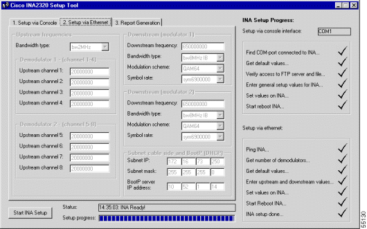
These are then automatically saved to the Cisco INA2320 by the Cisco INA2320 Setup Tool using SNMP. Proceed as follows:
Default: bw2MHz
An image of the corresponding cable layout appears (see Figure 3). You are then prompted to enter from one to eight frequencies, depending on the number of directions you have selected.
Step 2 Number of Downstream Channel Directions: Select the number of downstream channel directions that matches the configuration of your downstream network by clicking on the appropriate radio button:
Step 3 Number of Upstream Channel Directions: Select the number of upstream channel directions that matches the configuration of your upstream network by clicking on the appropriate radio button:
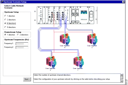
Step 4 Upstream frequency 1 ... 8: Type in the relevant number of upstream frequencies. Note that the first upstream frequency is also the frequency of the service channel. If the signal from this upstream channel is combined with other upstream channels, make sure that the frequencies do not overlap. When using 2 MHz bandwidth, the frequencies should be at least 2 MHz apart.
Valid range: 5000000 - 65000000 [Hz]
Default: 20000000
Step 5 Downstream Frequency: Type in the center frequency for the downstream channel.
For the Cisco INA2320 equipped with VHF upconverters (Arcodan module Type 94312):
Valid range: 118000000 - 450000000 [Hz]
For Cisco INA2320s equipped with UHF upconverters (Arcodan module Type 94313):
Valid range: 470000000 - 858000000 [Hz]
Default: 650000000 [Hz]
 |
Note Cisco recommends the VHF upconverter (Arcodan module Type 94312) for out-of-band (OOB) transmissions. |
Step 6 Bandwidth Type: Select the bandwidth and enter the parameters for the Cisco INA2320 downstream signal.
If you are connecting cable modems or set-top boxes (STBs) that support DVB In-Band signaling to the Cisco INA2320, select bw8MHz IB.
If you are connecting STBs that do not support DVB in-band signaling, select 1 or 2 MHz OOB.
Default value: bw8MHz IB
Step 7 Modulation Scheme: Select the modulation scheme for the Cisco INA2320 downstream signal.
If you are connecting cable modems that support DVB in-band signaling to the Cisco INA2320, you can choose any of the available modulation schemes, provided that they are supported by the cable modem.
For noise and network design reasons, Cisco recommends using QAM64.
If you intend to use the Cisco INA2320 on a microwave link or equivalent, Cisco recommends that you select the modulation scheme QPSK.
Default value: QAM64
Step 8 Symbol Rate: Select the symbol rate you want to use for the Cisco INA2320 downstream signal.
For In-Band operation, select 6.9 Msymbols/s.
For use with QPSK modulation, 6.875 Msymbols/s is typically used.
Default value: sym6900000
Step 9 Downstream 2: If you selected two downstreams, to add the second downstream, repeat Step 5 through Step 8 above.
Step 10 Subnet IP: Type the IP address to be used on the hybrid fiber-coaxial (HFC) interface of the Cisco INA2320 (primary subnet). This is the default gateway used by the connected cable modems or STBs and must be on a different subnet than the subnet for the Cisco INA2320 Ethernet IP address.
Default value: 192.168.2.1
Step 11 Subnet Mask: Type the IP subnet mask for the Cisco INA2320 HFC IP subnet (primary subnet).
Default value: 255.255.255.0
Step 12 IP address: Type in the IP address of the Dynamic Host Configuration Protocol (DHCP)/BootP server. This causes the Cisco INA2320 to forward DHCP/BootP requests directly to this IP address, rather than to use broadcasts. This is the primary IP helper address—from the Cisco Cable DVB/DAVIC Management Program. It is possible to enter a secondary IP helper address as a backup.
If you have no DHCP/BootP server on your network, or you do not want to direct DHCP/BootP requests directly to a specific IP address, leave the default value in this field.
Default value: 0.0.0.0
Step 13 You must now set the upconverter downstream frequency indicated by the Cisco INA2320 Setup Tool. Go to the Cisco INA2320 and identify which upconverter module you need to use, VHF or UHF.
 |
Note The upconverters are the Arcodan modules on the front panel of the Cisco INA2320. The VHF is Type 94312 (recommended for OOB use), and the UHF is Type 93313. |
Now follow these steps:
a. Simultaneously hold down the UP and DOWN buttons of the appropriate module until PROG MODE appears in the display (approximately 2 seconds).
b. Press the DOWN button to find the CENTER menu.
c. Press the ENTER button.
d. Press the UP or DOWN button to select the frequency XXX.XX MHz.
e. Press the ENTER button again.
f. Simultaneously hold down the UP and DOWN buttons until STORE DATA appears in the display (approximately 2 seconds).
Step 14 Now return to your setup PC and click OK on the Setup via Ethernet tab to continue.
Step 15 A new prompt appears advising you to click OK to reboot the Cisco INA2320 and thereby activate the new settings. If you are satisfied that you have entered the correct values, click OK.
The Cisco INA2320 now reboots. This can take up to 5 minutes.
When the reboot is completed, the Report Generation tab appears (see Figure 4).
This lists the values for each of the parameters you have entered. It also contains additional remarks concerning the router and Dynamic Host Configuration Protocol setup.
The report can be printed or saved as a text file, or both.
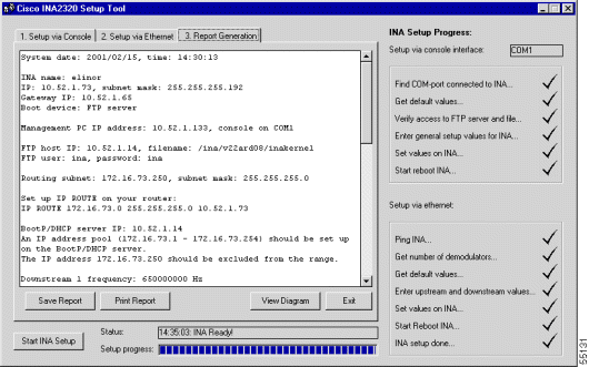 The Report Generation Screen
Clicking View Diagram causes a graphical representation of your specific network setup to appear (see Figure 5).
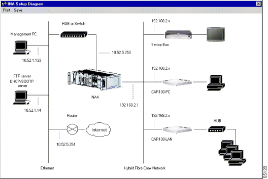
This diagram shows the IP addresses both on the cable and on the Ethernet side of the network. The diagram can also be printed by clicking the Print button.
AccessPath, AtmDirector, Browse with Me, CCDA, CCDE, CCDP, CCIE, CCNA, CCNP, CCSI, CD-PAC, CiscoLink, the Cisco NetWorks logo, the Cisco Powered Network logo, Cisco Systems Networking Academy, the Cisco Systems Networking Academy logo, Fast Step, Follow Me Browsing, FormShare, FrameShare, GigaStack, IGX, Internet Quotient, IP/VC, iQ Breakthrough, iQ Expertise, iQ FastTrack, the iQ Logo, iQ Net Readiness Scorecard, MGX, the Networkers logo, Packet, PIX, RateMUX, ScriptBuilder, ScriptShare, SlideCast, SMARTnet, TransPath, Unity, Voice LAN, Wavelength Router, and WebViewer are trademarks of Cisco Systems, Inc.; Changing the Way We Work, Live, Play, and Learn, Discover All That's Possible, and Empowering the Internet Generation, are service marks of Cisco Systems, Inc.; and Aironet, ASIST, BPX, Catalyst, Cisco, the Cisco Certified Internetwork Expert logo, Cisco IOS, the Cisco IOS logo, Cisco Systems, Cisco Systems Capital, the Cisco Systems logo, Enterprise/Solver, EtherChannel, EtherSwitch, FastHub, FastSwitch, IOS, IP/TV, LightStream, MICA, Network Registrar, Post-Routing, Pre-Routing, Registrar, StrataView Plus, Stratm, SwitchProbe, TeleRouter, and VCO are registered trademarks of Cisco Systems, Inc. or its affiliates in the U.S. and certain other countries.
All other brands, names, or trademarks mentioned in this document or Web site are the property of their respective owners. The use of the word partner does not imply a partnership relationship between Cisco and any other company. (0102R)
![]()
![]()
![]()
![]()
![]()
![]()
![]()
![]()
Posted: Fri Mar 30 03:47:06 PST 2001
All contents are Copyright © 1992--2001 Cisco Systems, Inc. All rights reserved.
Important Notices and Privacy Statement.